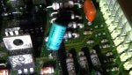
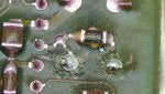
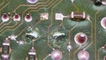
I have been chasing problems for a while and I finally found the problem, the ECM. It has 3 capacitors and you can visually check them. I had 2of3 that were bad. If you see the "green fuzz" it might be missing a leg on the capacitor... Thanks!!!

This is what a bad ECM looks like!!!
dustin2100

1 - 20 of 28 Posts
Joined
·
350 Posts
- Reaction score
- 14
- Location
- Oklahoma city
I have been chasing problems for a while and I finally found the problem, the ECM. It has 3 capacitors and you can visually check them. I had 2of3 that were bad. If you see the "green fuzz" it might be missing a leg on the capacitor... Thanks!!!
Attachments
-
 216.4 KB Views: 2,628
 -
 360.3 KB Views: 2,935
- Reaction score
- 536
- Location
- Nashville
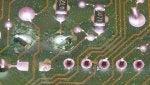
You are correct sir.Leaking,buldging and broken posts on the 3 electrolytic capacitors is the #1 most common failure component in the A9L,A9P,etc ecms.They normally go bad due to age,but moisture can also damage them.
Symptoms-some of the following symptoms will be present,if a capacitor is suspect.
1)No start
2)Hot no start
3)Hard starts
4)Intermittent misfires or surging
5)Excessively rich with black smoke from the tailpipe
6)Stalling
7)This last symptom is almost a guarantee youve got a bad capacitor:: Fuel pump running continuously when the key is turned on...........
You can get all 3 capacitors for under $5-$10 & solder them in yourself.
(2)47uf16v (1)10uf63v
Pay attention to polarity before you remove them because the new ones have to be installed the same way.Most guys will just go out & pay $150+ for a remanufactured ecm,but if the capacitors & sigrtn trace are the only things damaged & you repair it yourself,it'll only run you $10 or less,which is a $140+ savings,right.The link at the bottom talks about cap replacement.
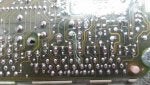
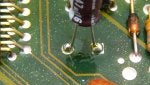
Another thing to check while youve got the cover off is a burnt (open) Signal Return trace.Its the 2nd most common failure component.A new piece of (I believe) 32ga wire can be soldered in place to repair this issue.Not being able to trigger a koeo/koer test with a scanner or a jumper wire installed between the STI terminal & SigRtn terminal,running excessively rich and having codes present for all sensors that share the SigRtn wire (act,ect,tps,evp,map/bp) is the symptoms that occur when this trace is burnt(open) Its shown in the pictures below.
2nd. case of three (3) A9L ECMs getting refurbished - Hackfabrication
Symptoms-some of the following symptoms will be present,if a capacitor is suspect.
1)No start
2)Hot no start
3)Hard starts
4)Intermittent misfires or surging
5)Excessively rich with black smoke from the tailpipe
6)Stalling
7)This last symptom is almost a guarantee youve got a bad capacitor:: Fuel pump running continuously when the key is turned on...........
You can get all 3 capacitors for under $5-$10 & solder them in yourself.
(2)47uf16v (1)10uf63v
Pay attention to polarity before you remove them because the new ones have to be installed the same way.Most guys will just go out & pay $150+ for a remanufactured ecm,but if the capacitors & sigrtn trace are the only things damaged & you repair it yourself,it'll only run you $10 or less,which is a $140+ savings,right.The link at the bottom talks about cap replacement.
Another thing to check while youve got the cover off is a burnt (open) Signal Return trace.Its the 2nd most common failure component.A new piece of (I believe) 32ga wire can be soldered in place to repair this issue.Not being able to trigger a koeo/koer test with a scanner or a jumper wire installed between the STI terminal & SigRtn terminal,running excessively rich and having codes present for all sensors that share the SigRtn wire (act,ect,tps,evp,map/bp) is the symptoms that occur when this trace is burnt(open) Its shown in the pictures below.
2nd. case of three (3) A9L ECMs getting refurbished - Hackfabrication
Attachments
-
 118.6 KB Views: 2,580
 -
 83.2 KB Views: 2,245
Joined
·
350 Posts
- Reaction score
- 14
- Location
- Oklahoma city
Oh man, I was very happy to find this! I was testing and the reference voltage was off on a few sensors and the car was not responding to obd scan. Yes, it ran like crap and didnt want to start. It would fire up and stumble then die. I am probably going to just get a reman unit from Cardone. Summit has them for $130 with a $70 core charge.
From what I have read, voltage spike is the biggest culprit for capacitor failure and it is usually caused by an alternator going bad. Possibly a bad battery making the alt work overtime. I do notice that my dome lights surge like they are on a dimmer switch. I have been thinking about a SN95 alt swap if the computer fixes my problems.
From what I have read, voltage spike is the biggest culprit for capacitor failure and it is usually caused by an alternator going bad. Possibly a bad battery making the alt work overtime. I do notice that my dome lights surge like they are on a dimmer switch. I have been thinking about a SN95 alt swap if the computer fixes my problems.
- Reaction score
- 536
- Location
- Nashville
Thats surprising.Most places you search are usually out of stock so you done good finding one.I never thought to check with Summit Racing though.Oh man, I was very happy to find this! I was testing and the reference voltage was off on a few sensors and the car was not responding to obd scan. Yes, it ran like crap and didnt want to start. It would fire up and stumble then die. I am probably going to just get a reman unit from Cardone. Summit has them for $130 with a $70 core charge.
From what I have read, voltage spike is the biggest culprit for capacitor failure and it is usually caused by an alternator going bad. Possibly a bad battery making the alt work overtime. I do notice that my dome lights surge like they are on a dimmer switch. I have been thinking about a SN95 alt swap if the computer fixes my problems.
If you couldn't get a scanner to trigger the koeo & koer test,thats usually an indication of a burnt (open) Signal Return trace on the ecm board.The black/white SigRtn wire,that runs to the tps,act,ect,map/bp & evp sensor,also runs between the diagnostic test connecter & the ecm (pinout #46) The scanner uses this wire as its ground to activate the koeo koer scan,so if this wire has an open in it between the diagnostic connecter & pin 46 at the ecm harness or inside the ecm itself,a scanner wont work.If I were you,I would check the SigRtn wire with an ohmmeter to make sure its intact.
Set the meter to read ohms,connect one meter lead to the SigRtn wire,at the diagnostic port,& connect the other meter lead to pin 46 @ the ecm harness (ecm disconnected) & take a reading.The meter should read 5.0 ohms or less.If its higher than that,the wire has an open between the two locations I listed.
The battery has to supply the alternator with at least 12.5 volts,in order for the alternator to function correctly.One thing you need to check is the secondary ground.Its the ground strap located between the driver cylinder head (rear)& firewall.Make sure its tight & corrosion free.This is the ground for the interior/exterior lights,ac compressor clutch,alternator and the gauges.
A bad secondary ground will cause::
1)Intermittent efi problems.
2)Headlights and interior lights will dim
3)Erratic gauge readings
4)Alternator overload (bad ground causes alternator to max out)
As you can see,several of your symptoms could be caused by a bad ground here
Check your dash lamp too.When you first turn the key on,does the charge indicator light come on briefly then turn off?? If it doesnt,you need to trouble shoot the circuit(check the wire for continuity and make sure the bulb isnt blown.If its blown,that will cause the alternator to not charge.The alternator harnesses have a fusible link on each one of them,so check their condition if a charging problem is occurring.
A move to a SN95 130amp alternator is definitely a good upgrade.If you click the following link then scroll down to the alternator section,youll find several good donor cars for this upgrade.
Junkyard Horsepower SUMMARY! - Ford Mustang Forums : Corral.net Mustang Forum
I work for an electronics firm and I deal with PCB's on a daily basis. That component can be replaced.Oh man, I was very happy to find this! I was testing and the reference voltage was off on a few sensors and the car was not responding to obd scan. Yes, it ran like crap and didnt want to start. It would fire up and stumble then die. I am probably going to just get a reman unit from Cardone. Summit has them for $130 with a $70 core charge.
From what I have read, voltage spike is the biggest culprit for capacitor failure and it is usually caused by an alternator going bad. Possibly a bad battery making the alt work overtime. I do notice that my dome lights surge like they are on a dimmer switch. I have been thinking about a SN95 alt swap if the computer fixes my problems.
Also from what I see the board is not too damaged. Whether or not another component was damaged or stressed
due to the cap failure is another issue, but you can repair it for very little money. Caps are cheap.
You have nothing to lose trying to repair it. If it doesn't work simply buy the remanufatured one
and send in yours as a core.
Joined
·
350 Posts
- Reaction score
- 14
- Location
- Oklahoma city
I was hoping that it was normal wear and tear on the car. I started to get nervous about the electrical system because I bought the car in Oct and I dont know much about it yet. We are getting to know eachother though... Now this guy had electrical problems!!!
http://www.allfordmustangs.com/forums/5-0l-tech/332661-ecu-fried-pics.html
I watched the EFI Guy's video and it turns out that he has ties to Moates QH somehow and he wants $50 for the repair. Really, I was happy that I found the video because I didnt think that you could visually inspect the ECM!
http://www.allfordmustangs.com/forums/5-0l-tech/332661-ecu-fried-pics.html
I watched the EFI Guy's video and it turns out that he has ties to Moates QH somehow and he wants $50 for the repair. Really, I was happy that I found the video because I didnt think that you could visually inspect the ECM!
Joined
·
350 Posts
- Reaction score
- 14
- Location
- Oklahoma city
I would like to be able to repair it, but I think that my hands are too shaky. 100% PTSD rating. It did cross my mind to see if a computer repair store could do it for cheap, but I doubt that they would want less than the EFI Guy wanted.
Joined
·
136 Posts
- Reaction score
- 12
Good video. I may see if he can repair mine from the '95.
Joined
·
350 Posts
- Reaction score
- 14
- Location
- Oklahoma city
Summit pushed my order back again today! I am about to order a nice soldering iron, desoldering wick, and capacitors. Shaky hands or not, I am going to give this a try!!!I work for an electronics firm and I deal with PCB's on a daily basis. That component can be replaced.
Also from what I see the board is not too damaged. Whether or not another component was damaged or stressed
due to the cap failure is another issue, but you can repair it for very little money. Caps are cheap.
You have nothing to lose trying to repair it. If it doesn't work simply buy the remanufatured one
and send in yours as a core.
Joined
·
350 Posts
- Reaction score
- 14
- Location
- Oklahoma city
I have a shopping list made for Amazon and I hope that these tools will be good enough... It is $75 for everything listed...
https://www.amazon.com/Weller-WLC10...UTF8&qid=1486788237&sr=1-1&keywords=Weller WLC100&tag=vs-auto-convert-amazon-20
https://www.amazon.com/gp/product/B..._sc_act_title_3?ie=UTF8&psc=1&smid=A13PRKMVKLJGWH&tag=vs-auto-convert-amazon-20
https://www.amazon.com/gp/product/B..._sc_act_title_2?ie=UTF8&psc=1&smid=A1UMBRA5ZTBCX8&tag=vs-auto-convert-amazon-20
http://www.mouser.com/Search/Produc...rch/ProductDetail.aspx?R=UPM1C470MDDvirtualkey64700000virtualkey647-UPM1C470MDD
http://www.mouser.com/Search/Produc...rch/ProductDetail.aspx?R=UPM1J100MDDvirtualkey64700000virtualkey647-UPM1J100MDD
Summit pushed my order back again today! I am about to order a nice soldering iron, desoldering wick, and capacitors. Shaky hands or not, I am going to give this a try!!!
That's the spirit. Give it your best shot. All the tools you are getting will do
the job nicely just take your time.
- Reaction score
- 536
- Location
- Nashville
Summit pushed my order back again today! I am about to order a nice soldering iron, desoldering wick, and capacitors. Shaky hands or not, I am going to give this a try!!!
For what the capacitors cost,its definitely worth a shot right?? Dont forget to check the SigRtn trace too while youre there.If the trace is not open on the board,you need to test the SigRtn (black/white) wire between the diagnostic port & the ecm harness (pin 46) Test for continuity(ohms)
The wire should measure 5.0 ohms or less.
1) If it doesnt,youll have to remove the wire loom/fabric tape from around the main wiring harness so you can inspect the SigRtn wire & find the open in it then splice in a new piece of wire to repair it.
#2) If the wire does measure <5.0 ohms,that means its ok.So if your inspection reveals that the SigRtn trace is good on the ecm board & the SigRtn wire is also good between the two locations above,theres one other component youll have to test.When you tried pulling codes with a scanner & had no success,that indicates theres an issue with some part of the SigRtn circuit or possibly a power transistor.So if youve tested the SigRtn circuit & found zero issues,another circuit has to be suspect.
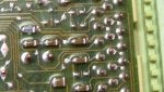
Once you finish replacing the capacitors & checking the SigRtn trace/wire at the ecm/wiring harness,connect the 60 pin harness to the ecm and screw the ecm ground wire back to the floor,but dont mount the ecm yet.Just lay it on the carpet for now,so you can verify if its functioning correctly before going through the hassle of installing it.You can see if the car starts & runs now.If it does,shut it back off then connect your scanner again and see if it will pull codes now.It might not show any codes since youve had it disconnected,but it should at least show a code 11 (system pass code) If the scanner still isnt working,youll have to remove the ecm cover again so you can test the power transistor I talked about earlier.The picture posted below shows the location of the transistor you need to test.I cant tell you how to test a transistor (never done it before) but this is the component you need to check.It cycles the STO ground pulses for the check engine light through pin 17.
The capacitors will hopefully get you back on the road again,but I suspect youll probably have a SigRtn repair to do also,because of how the scanner failed.
BTW- if a scanner doesnt trigger the koeo/koer tests and a jumper wire inserted between the STI terminal & SigRtn terminal doesnt trigger the tests,use the following method::
Insert a jumper wire between the STI terminal & the (-) battery post then connect a test light between the STO terminal & the (+) battery post.Turn the koeo & the test light should begin flashing the codes.If codes dont flash or the test light is lit continuously,that can be the sign for a bad transistor.
Good luck with your repair project.It'll hopefully cure your issues and save you a $130.
Attachments
-
 145.2 KB Views: 2,481
Joined
·
350 Posts
- Reaction score
- 14
- Location
- Oklahoma city
Oh man, I was hoping that it was the larger capacitor that was responsible for the signal communication! It would be the 2nd pic of the capacitors. Who knows, maybe all 3 are bad? I will see if I can find anything and if I find something questionable, I will take a pic and post it... Thanks!!!For what the capacitors cost,its definitely worth a shot right?? Dont forget to check the SigRtn trace too while youre there.If the trace is not open on the board,you need to test the SigRtn (black/white) wire between the diagnostic port & the ecm harness (pin 46) Test for continuity(ohms)
The wire should measure 5.0 ohms or less.
1) If it doesnt,youll have to remove the wire loom/fabric tape from around the main wiring harness so you can inspect the SigRtn wire & find the open in it then splice in a new piece of wire to repair it.
#2) If the wire does measure <5.0 ohms,that means its ok.So if your inspection reveals that the SigRtn trace is good on the ecm board & the SigRtn wire is also good between the two locations above,theres one other component youll have to test.When you tried pulling codes with a scanner & had no success,that indicates theres an issue with some part of the SigRtn circuit or possibly a power transistor.Since youve tested the SigRtn circuit & found zero issues,another circuit has to be suspect.
Once you finish replacing the capacitors & checking the SigRtn trace/wire at the ecm/wiring harness,connect the 60 pin harness to the ecm and screw the ecm ground wire back to the floor,but dont mount the ecm yet.Just lay it on the carpet for now.You can see if the car starts & runs now.If it does,shut it back off then connect your scanner again and see if it will pull codes now.Even if you dont have codes present,the scanner should still show a code 11 (system pass code) If the scanner still isnt working,youll have to remove the ecm cover again so you can test the power transistor I talked about earlier.The picture posted below shows the location of the transistor you need to test.I cant tell you how to test a transistor (never done it) but this is the component you need to check.It cycles the STO ground pulses for the check engine light through pin 17.
The capacitors will hopefully get you back on the road again,but I suspect youll probably have a SigRtn repair to do also,because of how the scanner failed.
BTW- if a scanner doesnt trigger the koeo/koer tests and a jumper wire inserted between the STI terminal & SigRtn terminal doesnt trigger the tests,use the following method::
Insert a jumper wire between the STI terminal & the (-) battery post then connect a test light between the STO terminal & the (+) battery post.Turn the koeo & the test light should begin flashing the codes.If codes dont flash or the test light is lit continuously,that can be the sign for a bad transistor.
Good luck with your repair project.It'll hopefully cure your issues and save you a $130.
Joined
·
350 Posts
- Reaction score
- 14
- Location
- Oklahoma city
It was hard to get a good pic for some reason. I am not using a phone but a camcorder that takes decent pics usually? Anyways, I didnt see anything like what was in the pic. I am really going to study the board and make sure though.You are correct sir.Leaking,buldging and broken posts on the 3 electrolytic capacitors is the #1 most common failure component in the A9L,A9P,etc ecms.They normally go bad due to age,but moisture can also damage them.
Symptoms-some of the following symptoms will be present,if a capacitor is suspect.
1)No start
2)Hot no start
3)Hard starts
4)Intermittent misfires or surging
5)Excessively rich with black smoke from the tailpipe
6)Stalling
7)This last symptom is almost a guarantee youve got a bad capacitor:: Fuel pump running continuously when the key is turned on...........
You can get all 3 capacitors for under $5-$10 & solder them in yourself.
(2)47uf16v (1)10uf63v
Pay attention to polarity before you remove them because the new ones have to be installed the same way.Most guys will just go out & pay $150+ for a remanufactured ecm,but if the capacitors & sigrtn trace are the only things damaged & you repair it yourself,it'll only run you $10 or less,which is a $140+ savings,right.The link at the bottom talks about cap replacement.
Another thing to check while youve got the cover off is a burnt (open) Signal Return trace.Its the 2nd most common failure component.A new piece of (I believe) 32ga wire can be soldered in place to repair this issue.Not being able to trigger a koeo/koer test with a scanner or a jumper wire installed between the STI terminal & SigRtn terminal,running excessively rich and having codes present for all sensors that share the SigRtn wire (act,ect,tps,evp,map/bp) is the symptoms that occur when this trace is burnt(open) Its shown in the pictures below.
2nd. case of three (3) A9L ECMs getting refurbished - Hackfabrication
Attachments
-
 337.4 KB Views: 1,829
Joined
·
350 Posts
- Reaction score
- 14
- Location
- Oklahoma city
- Reaction score
- 536
- Location
- Nashville
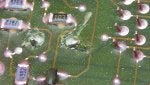
From what I can tell it seems to look good.This looks good, right?
I haven't tried it before,but I think you might be able to touch multimeter leads to each end of that printed trace to see if the meter reads a low ohms value.If you look at the pictures posted in that link that show where a new piece of wire was soldered in place to repair the open Signal Return trace & measure your trace between the two solder joints shown in that repair picture,if your trace ohms out at a low value that indicates the trace is not open.A high value or OL indicates the trace is open.Or if that doesnt work,you could measure from the actual pin(that the ecm wiring harness plugs into) on the ecm.You would wanna touch one meter lead to pin 46 then touch the other meter lead to pin 40 or 60.Pin 46 ties into both of those traces.
Joined
·
350 Posts
- Reaction score
- 14
- Location
- Oklahoma city
I should be getting my soldering tools in the mail today, excited! I got the capacitors yesterday and I have enough to at least do one practice run on a spare ECM that I have... I wish that I would have watched some of these capacitor videos a few months back because I threw away a Toshiba TV that probably needed a capacitor replaced. Toshiba repair was one of the big hits on Youtube and it was cool watching how other people solder and I picked up a few tips like using flux and the cheap solder suckers looked alright, but I will probably use the braid also... Anyways, I will be very stoked if I get my Mustang running right over the weekend!!! It would feel like an Allstar weekend for sure. OKC Thunder fan by the way
I should be getting my soldering tools in the mail today, excited! I got the capacitors yesterday and I have enough to at least do one practice run on a spare ECM that I have... I wish that I would have watched some of these capacitor videos a few months back because I threw away a Toshiba TV that probably needed a capacitor replaced. Toshiba repair was one of the big hits on Youtube and it was cool watching how other people solder and I picked up a few tips like using flux and the cheap solder suckers looked alright, but I will probably use the braid also... Anyways, I will be very stoked if I get my Mustang running right over the weekend!!! It would feel like an Allstar weekend for sure. OKC Thunder fan by the way
I can offer you one very important tip. Solder's melting point is
around 360 degrees. This is the point when it just starts to become
liquid. Considering you are going to use desoldering braid you will
need aprox 550 degrees in order for the braid to work. If you can
set your iron to 600 to 650 degrees that would be the correct temp.
Most important is the amount of time that heat is applied to the
pcb pad. Desoldering braid is notorious for lifting pcb pads if heated
for too long. Closely watch as the braid wicks up the solder. It should
take no more than 5 seconds. Any longer and you risk damaging the
pad. That is if you are using the correct size braid. The size you need
is one that is equal to or a little larger than the pad you are trying to clean.
Good Luck
Joined
·
350 Posts
- Reaction score
- 14
- Location
- Oklahoma city
So, I finally fixed my computer. It was not as difficult as I imagined and I actually enjoyed myself while working on it.
Everything seems fine now, but I am missing power at low RPM? It does not run like my '95 in my sig and it is supposed to be the same set up??? It sounded like the timing was off and I just got a new timing light not long ago. Maybe the previous owner forgot about the spout connector?
I did take my '95 block into a machine shop and got bored with new pistons, would that really make that much difference? I mean, my '95 is a screamer compared to my new '93 and it is the same top-end kit and a 302 vs 306... My '93 feels like it is not building power until 4,000RPM. The distributor appears to be OEM with a new TFI module. I took a peek at the oxygen sensors and they appear to be new along with most of the sensors like the IAC and TPS.
Joined
·
350 Posts
- Reaction score
- 14
- Location
- Oklahoma city
I checked the timing and it was set at 0, so I adjusted it to 10 BTDC with the spout off. It seemed like it was running better but it would not start back up. I had the OBD scan tool hooked up and I was getting a non-communication error again. Maybe I messed up the board, because it did smell a little like burned electronics??? I pulled the ecu again and I took pics starting with the ECU ground cable, it looks frayed but still intact.
Attachments
-
 346.2 KB Views: 1,399
 -
 354.4 KB Views: 1,261
 -
 348.8 KB Views: 1,226
 -
 358.3 KB Views: 1,208
 -
 348.1 KB Views: 1,153
 -
 310.5 KB Views: 1,143
 -
 315.4 KB Views: 1,124
 -
 289 KB Views: 1,234
 -
 345.9 KB Views: 1,175
 -
 329.2 KB Views: 1,085
1 - 20 of 28 Posts
-
?
-
?
-
?
-
?
-
?
-
?
-
?
-
?
-
?
-
?
-
?
-
?
-
?
-
?
-
?
-
?
-
?
-
?
-
?
-
?
- posts
- 3.7M
- members
- 240K
- Since
- 2001
A forum community dedicated to Ford Mustang owners and enthusiasts. Come join the discussion about performance, builds, modifications, reviews, engine swaps, classifieds, troubleshooting, maintenance, and more!
Explore Our Forums